CAN bus commercial vehicle interface
Take clean speed, reverse and status signals off a truck's network to trigger side-scan and blind-spot cameras, safety systems and body equipment.
What a commercial vehicle CAN interface does
A CAN bus commercial vehicle interface reads signals off a truck or large-van network, road speed, reverse, indicators and ignition among them, and provides clean outputs to trigger safety cameras and body equipment. It's how side-scan and blind-spot camera systems switch at the right moment on Direct Vision Standard and FORS camera builds, although compliance depends on the whole system.
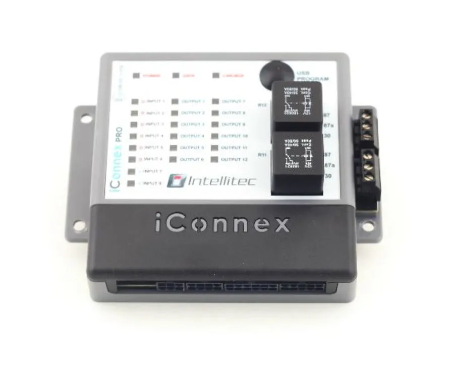
Heavy vehicles carry these signals digitally, so tapping the loom is awkward and risky. The interface reads the network instead, giving fitters a reliable, tidy way to add camera-monitor systems, sensors and warning equipment to an HGV.
Why HGV safety systems need a network interface
Direct Vision Standard and FORS push operators to fit camera-monitor systems, side sensors and audible warnings. Those systems need to know when the truck is turning, reversing or moving, and on a modern HGV that information lives on the CAN bus.
- Camera triggers off the network: switch side-scan and blind-spot cameras on the signals that DVS and FORS camera builds use.
- Left-turn and manoeuvre logic: trigger cameras and audible warnings from indicator and reverse signals.
- A clean HGV install: read the network rather than cutting into a heavy-vehicle loom.
- Body and equipment control: speed, reverse and status feeds for tail-lifts, cameras and ancillary kit.
What the interface drives
A commercial vehicle interface sits behind the safety and body systems on an HGV.
Side-scan cameras
Trigger nearside side-scan cameras on the left indicator for turning safety.
Blind-spot and 360 camera systems
Switch blind-spot and surround-view cameras on builds for Direct Vision Standard and FORS.
Reversing cameras and alarms
Bring up the rear view and sound a reversing alarm when reverse is selected.
Left-turn audible warnings
Trigger a spoken or audible turn warning from the indicator signal.
Tail-lifts and body equipment
Interlock body equipment to speed and status for safe operation.
Work lights and beacons
Switch working and warning lighting on sensible vehicle logic.
CAN KONTROL lines for trucks and buses
CAN KONTROL CV(opens in a new tab)
A standard FMS and J1939 signal set on CK-CV hardware for trucks, buses and heavy vans.
CAN KONTROL TACHO(opens in a new tab)
Provides a tachograph and D8 signal output taken from the vehicle bus.
CAN KONTROL PTO(opens in a new tab)
Reports PTO engagement so body-builder interlocks know when the drive is live.
Commercial vehicle lines at Intellitec MV(opens in a new tab)Compare with CANM8 product names


Fitting safety cameras to a commercial fleet?
Tell us the vehicles and the systems, and our engineers will confirm a clean interface off the CAN bus.
Reference
Fitting a CAN interface on a truck, bus or large van
Heavy vehicles bring 24V supplies, battery isolators and a standard signal set, plus operator and scheme requirements to check. This guide follows the order that keeps the fit clean and the camera or body equipment switching on the right events.
Tools for the job
- Digital multimeter rated for 24V
- Wiring information and the maker's body-builder guide
- Trim and panel removal tools
- Heavy-duty crimp tool
- Access equipment for working safely at height around the cab
Supplies to have ready
- Fuse and holder rated for the supply and the vehicle voltage
- Back-probe connectors for the CAN pair
- Relays or leads for the body equipment
- Heavy-duty loom, grommets and labels
- 1
Establish the voltage and isolator arrangement
Most heavy vehicles run 24V, and many have a battery isolator. Find out whether your supply point stays live when the isolator is open, because a module fed from the wrong side will lose power at the wrong moment.
- 2
Choose the signal set
Commercial vehicles publish a standard set over J1939, and fleet makers publish FMS on top. The CV line reads that set, the TACHO line gives a tachograph and D8 signal output, and the PTO line reports PTO engagement. Pick by the job.
- 3
Find the bus access point by class
Large vans and trucks often provide a cab-side connector for the fleet-management network, a diagnostic socket and sometimes a body-builder interface. Coaches and buses follow their own layouts. The maker's body-builder guide is the best guide.
- 4
Check whether the output is enabled
Some makers restrict their fleet-management output until it is enabled in the vehicle, so ask the maker or a dealer whether anything needs switching on before you rely on it.
- 5
Identify the pair and connect
Tag high and low, confirm the pair is alive, and connect with back-probes or the inductive reader. The vehicle has to remain compliant and serviceable, so make no cuts in the bus wiring.
- 6
Fuse, supply and earth
Feed the module from a fused permanent supply at the vehicle's voltage, and earth to a proper chassis point. Remember the isolator when you choose where each connection goes.
- 7
Wire the body equipment and cameras
Connect outputs to the camera control, side-scan trigger, alarm or body equipment, using relays where the load needs it. For camera systems, give indicator and reverse triggers their own labelled outputs.
- 8
Test, record and brief the driver
Record the connections and the configuration, and explain to the driver how the camera or body system should behave in service.
Checks before the vehicle returns to service
- Switch on the ignition and confirm the signals you need appear: speed, reverse, indicators and any PTO status.
- Signal left, then right, and confirm the matching side-scan or blind-spot view appears.
- Select reverse and confirm the rear camera and any alarm respond.
- Engage and release the PTO, if fitted, and confirm the reported state follows.
- Open and close the battery isolator and confirm the module recovers cleanly and nothing is left running.
How the commercial vehicle interface works
It reads the truck's own signals and triggers the safety and body systems to match.
- 1
Connect to the network
The interface joins the commercial vehicle CAN bus and reads speed, reverse, indicator and ignition messages, with no cut into the loom.
- 2
Decode the signals
It identifies the manoeuvre and status signals for that make and model of truck or large van.
- 3
Trigger the outputs
It switches clean outputs to activate side-scan and blind-spot cameras, alarms and body equipment on the right conditions.
- 4
Bring up the right view
The camera-monitor system shows the correct view and the warnings sound when the vehicle turns or reverses.
Which vehicles it covers
Speed, reverse, indicator and status signals are carried on the CAN bus of modern trucks and large vans, across the main HGV and commercial makes. The interface reads each manufacturer's messages in configuration, so one product covers a mixed commercial fleet.
Coverage spans the common UK truck and van fleet, kept current with in-house firmware. Scorpion has built vehicle electronics in the UK since 1973, and our group company Intellitec MV builds power and control systems for demanding commercial and specialist vehicles.
Side-scan cameras cover the nearside blind spot on a left turn, the classic risk to cyclists and pedestrians in town. A clean interface makes them switch automatically on the indicator, so the driver sees the nearside view exactly when it matters.
Beyond cameras, the same signals drive reversing alarms, work lights and body equipment. For the warning-lighting side, see the beacon and work-light control; for a full multi-signal fit, the multi-output interface.
Common fitments include:
Common questions
What is a CAN bus commercial vehicle interface?
It is an interface that reads speed, reverse, indicator and status signals off a truck or large-van network and provides clean outputs to trigger side-scan and blind-spot cameras, alarms and body equipment.
How does it help with Direct Vision Standard and FORS?
It switches side-scan and blind-spot camera systems from the vehicle's own signals, which camera builds for those schemes rely on. Compliance depends on the whole system and on the scheme's rules, so check the requirements that apply to your vehicle and operator.
Can it trigger a side-scan camera on a left turn?
That's a common setup: the interface reads the indicator signal off the network and can bring up the nearside view when the driver signals left. Availability depends on the vehicle, so confirm the make, model and year with us first.
Does it work across different truck makes?
The interface reads each manufacturer's messages in configuration, so the same hardware can be set up for different makes. Which signals are available depends on the vehicle, so tell us the make, model and year before you order.
Can you develop for a specialist commercial vehicle?
Yes. We design and manufacture CAN electronics in the UK, and our group company Intellitec MV builds control systems for specialist commercial vehicles. Speak to us about the fleet.
Why do I see nothing on the fleet-management pins?
Check whether the maker needs the output enabled, then confirm you're on the right connector and the correct pins from the body-builder guide. Test the supply and earth and look for a swapped pair. Tell us the make, model and year if the output is still silent.
Why doesn't the side camera come up on a left turn?
Check the indicator output goes to the right camera input, and that the vehicle reports the indicator message on the network you've connected to. Test both indicators separately and compare with the hazard-light behaviour.
Why does the module lose power when the isolator opens?
It's fed from the isolated side of the supply. Move the feed to a point that stays live, or accept that the module will drop out with the isolator, and plan the equipment around that.
How do J1939 and FMS differ for a body builder?
J1939 is the underlying heavy-vehicle CAN standard, and FMS is a fleet signal set published on top of it by the makers. Both give consistent access to signals, but what each vehicle publishes varies.
Will a camera build meet Direct Vision Standard or FORS requirements?
The camera and trigger logic are one part of those schemes. Compliance depends on the whole system and on the scheme's own rules, so check the requirements that apply to your vehicle and operator.
Why do the signals change when a trailer is attached?
Some heavy-vehicle signals, including trailer and lighting status, change when a trailer is connected. Test the system with and without a trailer, and tell us if the behaviour differs.
Does the tachograph signal from this module replace a tachograph?
No. The line provides a tachograph and D8 signal output taken from the bus, for use with a tachograph system. Tachograph fitting and calibration belong to the tachograph maker and approved workshops.
Does it suit a coach or bus as well as a truck?
Buses and coaches carry the same standard signal sets. Layouts differ widely, so give us the make, model and year of the vehicle.